Showing posts with label boat repair. Show all posts

Tuesday, 16 August 2016

MUST HAVE INFO 4 COBRA OWNERS

  MUST HAVE INFO 4 COBRA OWNERS


DO YOU HAVE A COBRA STERNDRIVE? IF SO YOU WILL WANT TO HAVE THIS! 


THIS INFORMATION FROM:

OMC Cobra Sterndrive Tech Info

Disclaimer

This website and its author are not affiliated in any way with OMC. See complete disclaimer below.

Introduction and History

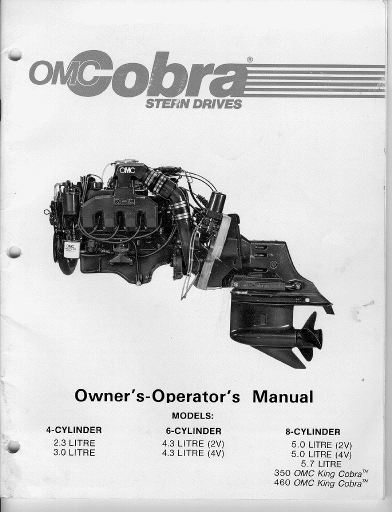
When some critical Volvo patents expired, Outboard Marine Corp. redesigned their sterndrive product and named it the "Cobra." This sterndrive was mated to many different engines, and was routinely installed on a wide variety of boats. The first Cobra shipped in 1985. Everyone agreed the new Cobra drive was an improvement over the predecessor "stringer mount" drive, including many existing boat manufacturers that owned large inventories of the now-obsolete drives. Since these manufacturers didn't want to get stuck with un-salable sterndrives, they pressured OMC into limiting Cobra shipments until they could clear out their existing inventories. Thus, the Cobra didn't ship in volume until the 1986 model year. Thanks to Carl G. Craver for this tidbit. Some early Cobras ate their gearsets. OMC initially thought the clutch dogs were disengaging due to insufficient "bite" (interference cut) on the clutch dog teeth. OMC increased the bite angle from two to five degrees, and all subsequent Cobra clutch dogs have five-degree teeth. All known Cobra owners got a letter (133k) promising warranty coverage if any gearsets failed. Unfortunately, the five-degree clutch dogs did not solve the problem, and in the following year, OMC re-diagnosed the trouble as sticky shift cables. Cobra owners got another letter, inviting them to deliver their boats to an OMC dealer for a free redesigned cable. OMC would replace any cable that failed for free, and if a cable failure destoryed a gearset, OMC would replace the gearset too. The last time I checked (1997), a Cobra gearset was almost US$1000 (labor extra). OMC finally ended this extended warranty in early 1994. I belive the redesigned cable has truly fixed the problem. Alas, many people in the marine business clearly rememberd the gearset troubles, and forgot (or never heard of) the subsequent cable recall and resolution. Many of these folks are "still around," and they have contributed to the Cobra's (undeserved) troubled reputation today. The Cobra was produced until 1993, when OMC redesigned it to use a cone-clutch shifting mechanism originated by Volvo-Penta. I don't know if OMC purchased gears and etc. made by Volvo, or just copied Volvo's design. OMC was having financial difficulties at that time, and sold a 50% stake in their sterndrive business to Volvo-Penta. This new sterndrive is available with one prop ("SX") or dual props ("DP"). The new SX/DP drive retains many of the original Cobra castings. OMC has since been taken private by another company, and sold their remaining interest in the sterndrive business to Volvo. OMC and Volvo have agreed to supply parts to each other, but OMC has left the sterndrive business. OMC continues to purchase SX and DP drives for boats produced by OMC subsidiary companies. OMC went bankrupt in December 2000. Bombardier has purchased the outboard business and the Evinrude and Johnson brandnames. Bombardier is supplying Cobra sterndrive parts, with some price increases. My understanding is that OMC still exists as a legal entity, but they've closed their business, and sold off the rights to their products. I gather they still own their Waukegan headquarters, mainly because they polluted it badly and it's now a Superfund site.

Problems with the Cobra

Cobras have a reputation for eating their gears. This is usually due to a failed shift cable, and is easily prevented. Cobras are routinely maladjusted, compounding the problem. When the distraught owner of a failed Cobra wrote to Trailer Boats magazine, they brushed him off. I wrote a followup letter to Trailer Boats to explain what happened. My letter suggested the dealer was responsible, but it was never published; I suppose it was too long. You may read it here.

Current Status of the Cobra

Original and aftermarket parts seem to be readily available. Comments on rec.boats suggest that many dealers and technicians are still misunderstanding Cobras, and I expect that Cobra expertise will diminish over time. If you're buying a used boat, you're stuck with the drive already installed. If it's a Cobra, you can use the information here to get it shifting perfectly; properly maintained, it is just as good or better than the comparable MerCruiser products. The terrible reputation of the Cobra may depress the price of Cobra-equipped boats slightly. If you know how to adjust a Cobra, this is not an entirely bad thing.

Identifying Your Cobra

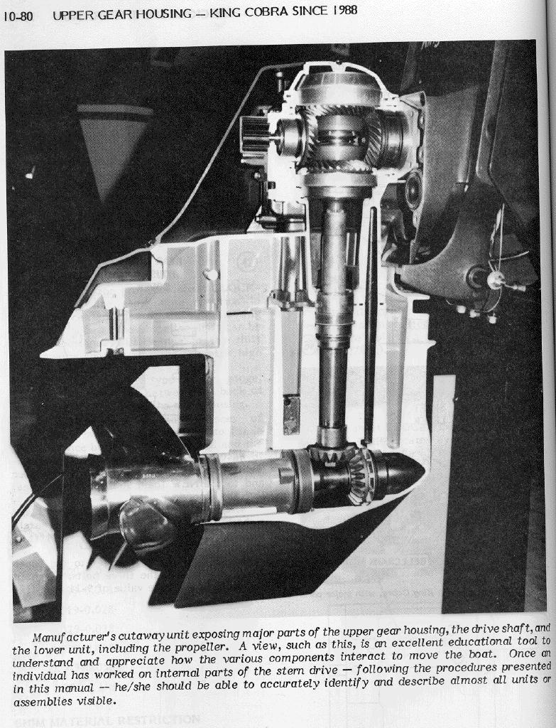
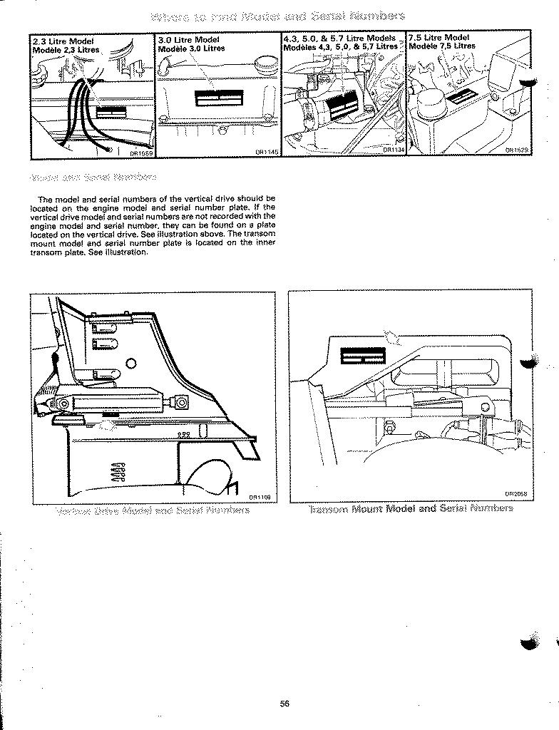
I'm aware of three varieties of Cobra: 1. Dog-clutch (128k), prop exhaust (labelled "OMC Cobra") The most common Cobra, and the subject of this website. The F-N-R gears are located in the bottom, in-line with the propeller. Note the top of the outdrive (portion exposed to water outside the boat) is relatively flat. 2. Dog-clutch, through-hull exhaust (labelled "King Cobra") Mechanically the same as #1, but louder. 3. Cone-clutch (cut-away view, 198k) (also labelled "King Cobra") This Cobra is very rare; I have never personally seen one. The F-N-R gears are located in the top of the outdrive, directly behind the engine. Note the hump on top of the outdrive case that accomodates these bulkier gears. The Volvo-style "cone clutch" in the 1993-on "King Cobra" is extremely durable, and it is not subject to the "bad gears" failure the others are famous for. The 1993-on "King Cobra" is also not otherwise addressed on this webpage; if you have one, buy the manuals, and take it to a qualified Volvo technician. Rejoice! Volvo-style gears are renouned for near-indestructibility. Note the water-pump located on the back of the F-N-R gearcase on the 1993-on OMC "King Cobra." I've been told that the Volvo SX and DP drives use a similar waterpump attached to the engine crank pulley (inside the boat). The rest of you with "dog-clutch" Cobras can continue reading :-) . You will need your serial numbers when querying OMC about your drive. OMC hid several different serial numbers in various places. See them all here (141k). This page was scanned from my 1998 Owners' Manual, and does not show where OMC hid the serial number for smallblock Ford V8s (302, 351), or for GM big-block V8s (454, 502).

Whats a Dog Clutch?

Clumsily explained here.

My Own Cobra Experience

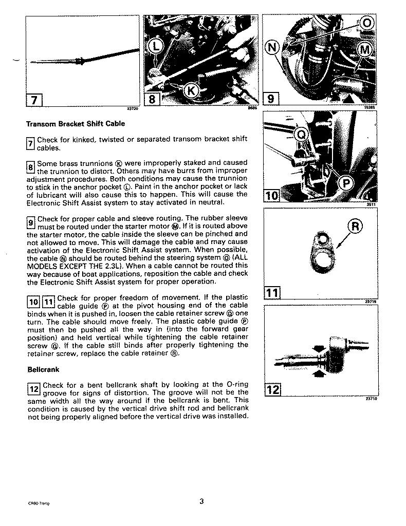
My Cobra has a 2bbl 4.3L V6, and is fitted to a 1988 Four Winns Horizon 180, a typical 18-foot bowrider. This is my first boat, so it took me a while to realize what a serious problem I was facing. My Cobra gearshift was very stiff, requiring about three times as much force as it should to engage/disengage gears. I made many phone calls to OMC, accumulated documentation, talked to many people, and replaced parts until it improved. The main problem turned out to be the Transom Bracket Shift Cable; it seems that the cable OMC installed in 1989 during the recall was still on my boat, and it was failing. In retrospect, this should not have been a suprise; the cable was approximately nine years old! Today, my Cobra "shifts with a finger," as should any properly adjusted Cobra. My Cobra also had a stalling problem when cold; if you engaged a gear before the engine was fully warmed up (a ten-minute process), it would stall. This was an annoyance, as well as an embarrassment when there is a line of folks waiting to launch their boats. The stalling problem turned out to be a vacuum leak, coumpounded by a complete carburetor maladjustment. Of course, I didn't figure this out until I removed the carburetor for a rebuild (one of the hold-down nuts was loose). It appeared that a previous owner/mechanic deliberatly maladjusted everything on the carburetor in a vain attempt to compensate for the vacuum leak. Today, I can engage reverse and back off the trailer as soon as the engine is running. When reviving my boat from winter storage in 1999, I carefully re-visited the adjustment procedure, and I actually measured the cable drag of my transom bracket shift cable. It was too high; another hour of exploration led to a defective "retainer" (see part "R" in picture 11 here). I thought this was very subtle problem, but it's known and documented in the OMC service bulletins. I have some hints for Cobra owners that defy classification. If you have any of your own to share, please send me an e-mail.

Adjusting your Cobra Shift Linkage

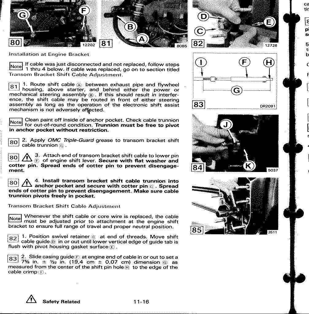
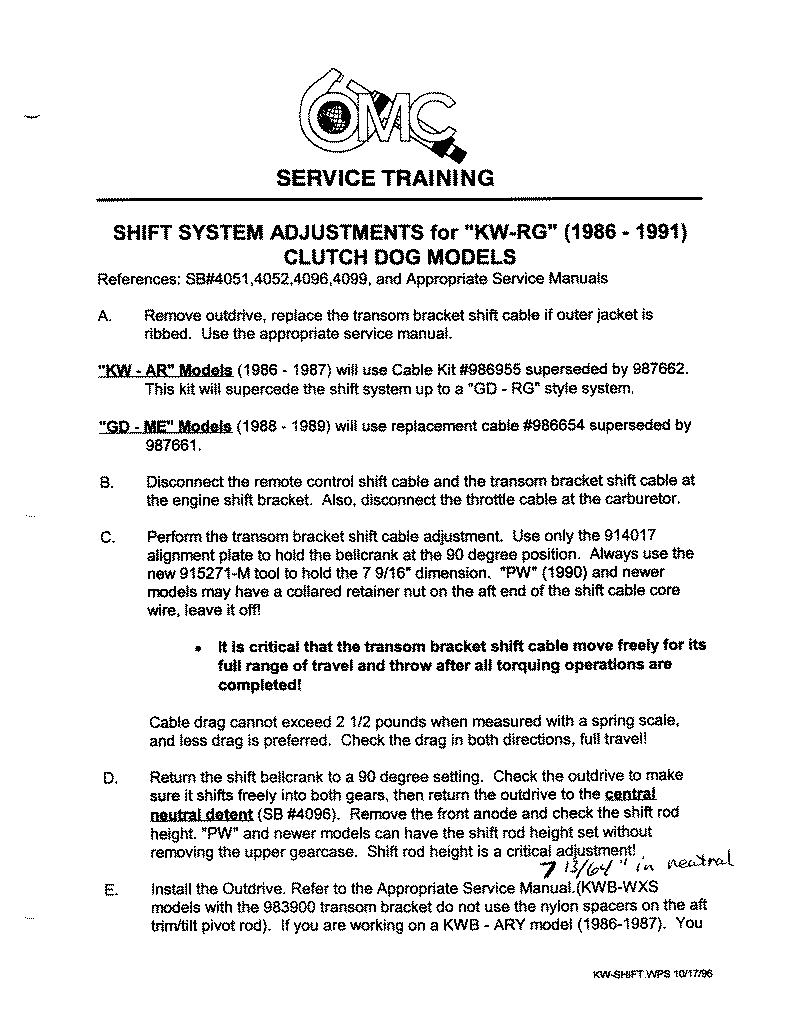
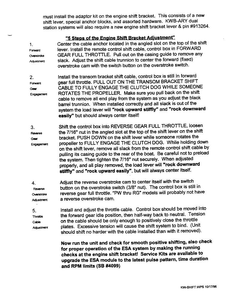
Dave Brown (marina owner and frequent contributor to rec.boats) once said that a properly adjusted Cobra will "shift with a finger." I urge the reader to demand as much from your own sterndrive. If your sterndrive requires more than one finger to shift, get it fixed soon, because your gearset depends upon it. If you're serious about working on your sterndrive, I urge you buy all of the appropriate documentation, especially the "shop manual." I strongly recommend you get the original documentation from the people that built your equipment. I'm not impressed by the aftermarket manuals (Clymer, Seloc, &etc). The manuals should be available from your local dealer, or you can call the manufacturer directly and pay with a credit card. The price will be similar; locally, you'll pay sales tax, and if you order from the manufacturer, you'll pay shipping. Even if your shop manual is out-of-date in some respects (as mine is), it is a wealth of information, and very useful when diagnosing an obscure problem. I'm not listing part numbers for the documentation here because OMC may have different manuals that apply to different years of drives, and I'm too lazy to confirm or disprove this with OMC. However, here are the names of the documents I recommend you get: OMC Cobra Owner-Operator's Manual OMC Cobra Service Manual OMC Cobra Parts Catalog The third item may surprise you; it's a booklet of exploded parts diagrams for an entire sterndrive, with part numbers. This makes it very convenient to order parts from a dealer; you can order by part number, avoiding the usual colorful "thingy that connects the whatsit to the thingamgig" discussions. Below is a link to my by-hand transcription of an OMC document that explains how to adjust the shift linkage on the Clutch-Dog Cobra. I believe this procedure supercedes the procedure outlined in the OMC Cobra Service Manual. My copy of the OMC document is dated "10/17/96", and I believe it to be the latest and final word OMC will ever utter on this topic. Fortunately, it is reasonably clear and easy to follow, and I am very satisifed with my results. I hope this information is as helpful to others. When you read this document, be aware that it assumes you have a servicable Transom Bracket Shift Cable installed and adjusted correctly. If you are replacing your Transom Shift Cable, you'll need to adjust it with the ponderously-named Transom Bracket Shift Cable Adjustment procedure from the OMC Cobra Service Manual (page 11-16 in my copy). I have the two applicable pages 11-16 (290k) and 11-17 (288k) here. This procedure requires only common wrenches, a straightedge, and a ruler; note that subsequent Service Bulletins from OMC require you to use special Cobra-specific tools to make this adjustment.

Here is the legendary how-to-adjust-your-Cobra-shift-linkage document (what your dealer never told you, or didn't know):

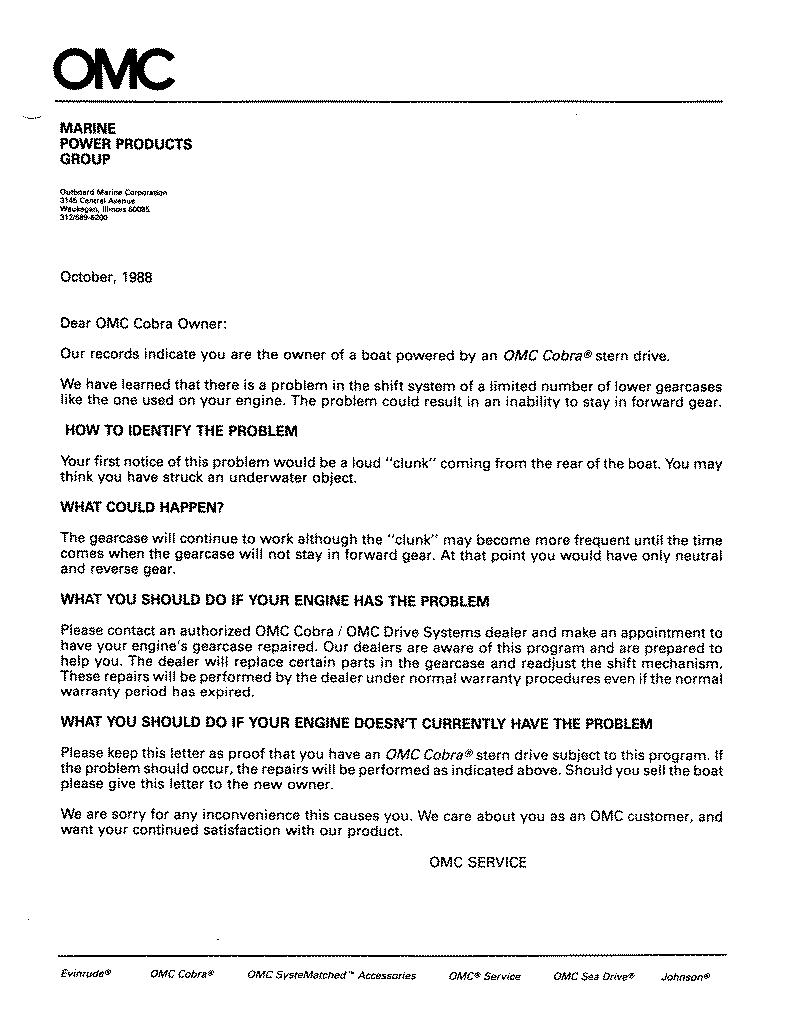
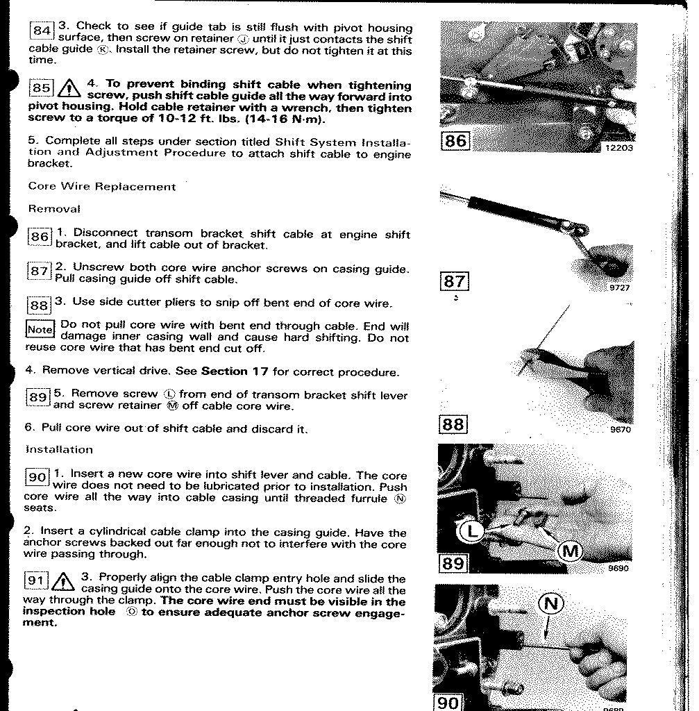
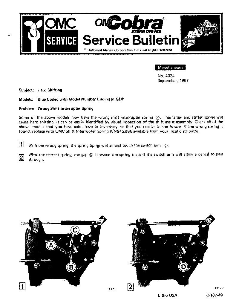
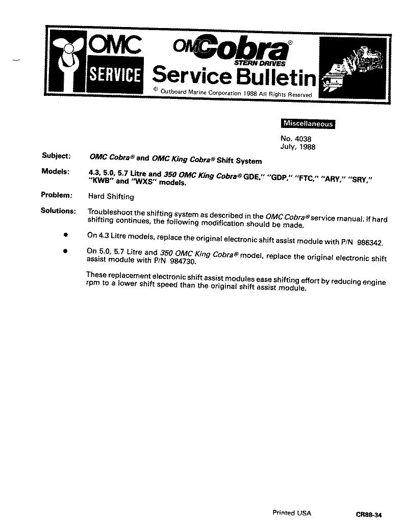
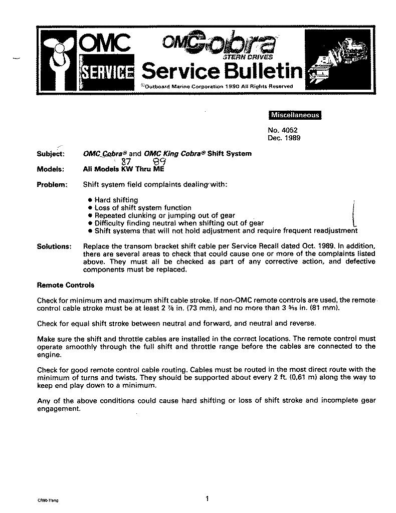
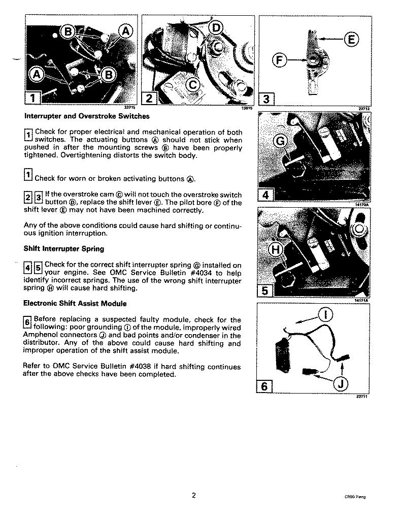
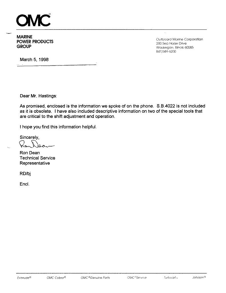
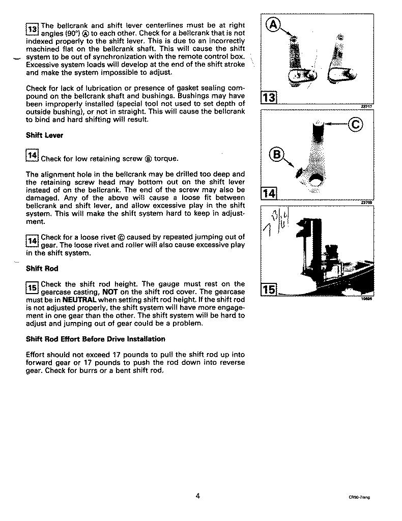
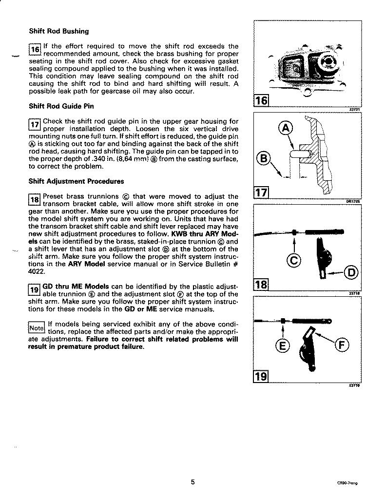
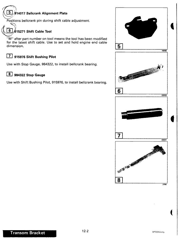
OMC Cobra Shift System Adjustments for "KW-RG" (1986-1991) Clutch Dog Models (Stuart's transcription; 10k HTML) Here are images of the of the original two-page document, provided so readers may see it, and point out any errors in my transcription: OMC Cobra Shift System Ajustments for "KW-RG", page 1 (160k) OMC Cobra Shift System Ajustments for "KW-RG", page 2 (201k) This Service Bulletin describes how to recognize a defective spring in the Cobra shift linkage, and the p/n of the correct replacement. It cost me about US$2.50 for this part, but the new spring was still too stiff. However, it's straightforward to crunch the spring by hand to get a more appropriate tension: "Wrong Shift Interrupter Spring" (120k JPEG) This Service Bulletin just says to install the latest ESA (Electronic Shift Assist) module. When OMC converted from a two-degree clutch dog to a five-degree, the dog was more reluctant to disengage. The new ESA makes the engine idle slower and weaker to make disengagement easier. If you have the original two-degree gearset, and your ESA works, you probably don't need the new ESA. "Hard Shifting" (95k) This is a catch-all of typical problems that make the Cobra hard to shift. My own unit had none of these problems, yet I found these pages very interesting; some very obscure and un-intuitive problems are explained here: Diagnosis of Cobra shift problems, page 1 (140k) Diagnosis of Cobra shift problems, page 2 (180k) Diagnosis of Cobra shift problems, page 3 (197k) Diagnosis of Cobra shift problems, page 4 (155k) Diagnosis of Cobra shift problems, page 5 (170k) This is a page with pictures of some special tools OMC recommends for working on the Cobra shift linkage. According to OMC, you must have these tools in hand before you can adjust your Cobra shift linkage. My own experience is that none of these tools are necessary, although I'm sure they would make the procedure faster and more convenient. Recommended Tools for adjusting the Cobra shift linkage (76k) Just for completeness, here's a letter that came with some of the service bulletins that OMC graciously sent to me: OMC Letter to Stuart (55k) Here is the letter informing Cobra owners of the gearset recall. I I was fortunate that the original owner of my boat kept this now-historic document. I believe there was a subsequent Transom Bracket Shift Cable Recall letter, but I do not have a copy; presumably it was given to the dealer when the cable was replaced. OMC Gearset Recall Letter (133k)

Pertronix Ignitor

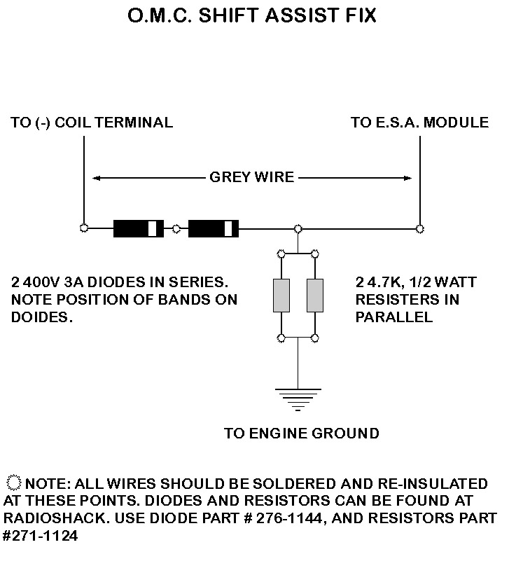
Many Cobras were built with non-electronic ignitions, using conventional points. These ignitions work fine, but the points are subject to wear, so the boat needs re-timing or even new points every season. You can end this cycle of maintenance by installing an electronic igntion retrofit; this is a gadget that replaces the points in your distributor. You install a plastic ring with magnets over the distributor cam, and the gadget senses the magnets as the distributor rotates. The beauty of the system is there are no points to wear and go out of adjustment, and I suppose it's a little more tolerant of moisture. OMC installed such "point-less" ignitions in the later Cobras (I've seen a '92 Cobra with factory electronic ignition). One option is to purchase this and mate it with your boat; in fact, OMC had a set of "kits" that included an electronic ignition gadget plus a new Electronic Shift Assist (ESA), all for the price of the ESA alone. I don't know if these are still available now that OMC is gone. Another, cheaper option is to install the Pertronix Ignitor(tm). (See http://www.pertronix.com.) This is problematic, as the OMC ESA expects to see its sense line dragged down to zero volts every time the points "close," and the Pertronix gadget doesn't do that. Your engine will run fine, but the ESA won't see the pulses it expects, and it won't work, so shifting is stiff. I telephoned Pertronix tech support (the phone number used to be on their website) and inquired. They said the OMC ESA was a known problem, and they mailed me a sheet with instructions for a simple circuit that would interface their gadget to the OMC ESA. Specifically, the circuit has two identical resistors, and two identical diodes, for a total of four parts. I visited my local Radio Shack, bought the parts, plus a small plastic box, and built the circuit. I installed it with my Pertronix Ignitor(tm), and my ESA works fine with it. The diagram that Pertronix sent me is here (100k). I grabbed this off their website some time back, and it subsequently disappeared. However, it had reappeared when I checked in early 2003 (look for "Ignitor," then "Support").

This Web Page

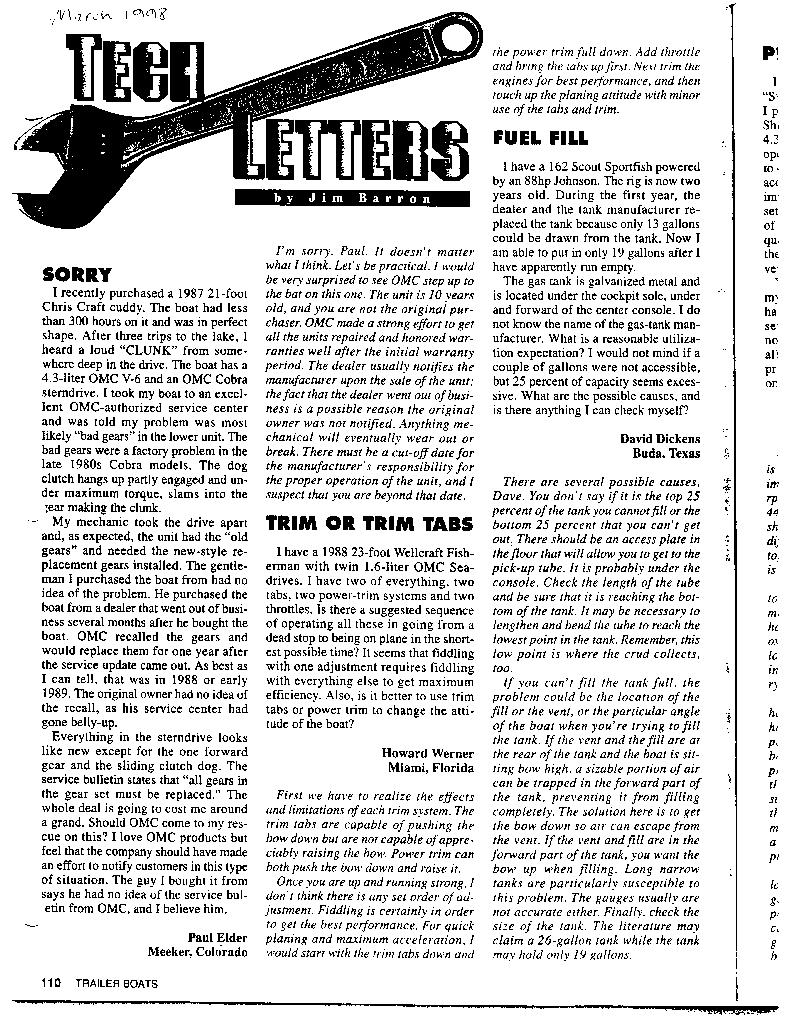
My intent in creating this web page is to spread what I've learned about the Cobra to other Cobra owners, that others may profit from what I've learned. I'm doing this as a Public Service; I'm not selling anything, or making any money with this information. I'm not trying to criticize anyone or force any changes in any corporate policies; I'm fighting ignorance. I did not create this web page to deprive OMC of documentation sales, or to save a few bucks for Cobra owners too cheap to buy the manuals, or to deprive OMC dealers of service business. If you own a Cobra, and you want to work on it yourself, you already know why you need the shop manuals. I realize, however, there are many people that are considering the purcase of a boat with a Cobra drive, or have been putting off the purchase of some manuals, or were just curious,& etc. Sadly, there are still many OMC dealers and independent technicians blissfully unaware of this information, and occasionally a Cobra gearset is destroyed due to such ignorance. Such incidents are expensive for Cobra owners, and they help propagate the "bad gears" story. For example, here is a letter (297k) from the March 1998 issue of Trailer Boats Magazine documenting such a case. If you spot an error, or have any suggestion for improving these pages, please send me a note. I'm reluctant to put my exact email address here, due to spamming concerns, but I'll spell it out: "stuart at hastings period org."

Legal Disclaimer

This information is provided as a Public Service; nobody is making any money from this. This website and its author are not affiliated in any way with Outboard Marine Corporation (OMC). OMC disavows any responsibility for this website, and the information herein. Neither OMC nor Stuart Hastings warrantee this information, and we accept no responsibility for any consequences if you attempt to apply any of the information stored here. OMC has looked at this website. When I created this website, I sent OMC an email describing this location and content. An OMC representative responded with this letter, graciously explaining OMC's position. I have already addressed the issues raised in the letter; you're reading the disclaimer. Please understand, dear reader, that I have reproduced OMC technical documents here, documents that OMC could claim copyright protection for. OMC has graciously agreed to tolerate this practice. Now that OMC is gone, I suppose Bombardier owns these documents; either way, I can't guarantee they'll stay available here forever. Given the fickle and ever-changing nature of the Web, this site will not exist forever. If you own, or expect to own, a Cobra sterndrive, I humbly suggest you make personal copies of any/all informtion contained here that seems useful to you. Created 19feb1999 Added Pertronix stuff, OMC bankruptcy, 03feb2003 Updated 23jun1999


To guarantee access to all of  Boat Nut Magazine articles, pictures and featured services visit the official Boat Nut Magazine ©™ website. Be sure to reply to the Boat Nut Association registration on our site for the latest Boat Nut weekly and monthly news letters and opportunities.


Copyright 2015 © Boat Nut Media, Toronto, Ontario. All rights reserved. No part of this information/publications may be stored in a retrieval system, transmitted, or reproduced in any way, including but not limited to photocopy, magnetic, or other record, without prior agreement and written permission of the publisher, Boat Nuts Media ©™ No liability is assumed with respect to the information provided

Friday, 12 August 2016

LIFE JACKET DESIGN WINNERS


Life Jacket Design Competition Winners
 

2015 Life Jacket Design Competition Winners Announced

 
Sponsored by the BoatUS Foundation for Boating Safety and Clean Water and the Personal Floatation Device Manufacturers Association (PFDMA), the 2015 Innovation in Life Jacket Design Competition attempted to answer the question: What would a modern life jacket look like if you threw out the rulebook and started with a clean slate?
The goal of the competition was to rethink a 100-year-old design, seek out the newest technologies and design innovations and develop interest in newer, more versatile life jackets. Design entries were judged on the following criteria: innovation, wearability, value/affordability, reliability, versatility and practicality.
A team of five judges from the boating, paddling and life jacket manufacturing industry reviewed nearly 250 contest submissions from as far away as Mongolia and New Zealand, and also asked recreational boaters to vote for their favorite design entry.
Competition Judge and Image Base Vice President Joe Fogarty said, “Whether a commercial enterprise, an individual inventor-entrepreneur, a student or a group of Scouts, the 2015 Life Jacket Design Competition brought forth a lot of creativity. The entries we chose will not only keep us afloat, but showed thoughtfulness, problem solving and practicality.”
Judge Lili Colby, Owner and “chief PFDiva” at paddlesport life jacket manufacturer MTI Adventurewear said, “It was exciting to see that so many of the competitors shared a common goal to create more wearable product for the average recreational boater. Thinking ‘out of the box’ not only meant that the designs need to work, but that they also need to look good and be comfortable to wear. I wouldn’t be surprised to find a number of the finalist’s designs make it to market someday if they can be US Coast Guard approved.”
Winners of the design competition received a share of $15,000 in prize money: $10,000 to First Place, $3,000 to Second Place and $2,000 to Third Place.

Winner Announcement Video:


Here is a breakdown of the three winners:

life jacket design winner

First Place: Michael Garman – Foam Filled Jacket

Michael Garman of Moseley, Virginia submitted his prototype design that uses two-part expanding foam encased in a comfortable thermal fabric that’s designed to keep the wearer cool. The design uses a smartphone app to submit exact body measurements to the factory where the lifejacket is custom molded, offering a perfect fit right out of the box. A heat reflecting fabric can be used on cold days to help keep the wearer warm – or reversed for hot days that combine with an inner fabric mesh to keep the wearer cool. Accessories such as a rear mounted hydration pack – great for paddlers – and custom pocket choices add versatility. A built-in signal mirror and whistle improve safety.


lifeshirt floatation device

Second Place: Jimi Beach of Aegis Safety Products – Life Shirt

Jimi Beach of the two-year-young Aegis Safety Products in Orlando, Florida took second place with his brand new, soon-to-market, inflatable floatation “Lifeshirt” that blends affordability with comfort and performance. The “actionwear” design looks similar to a sport shirt and is intended for a range of uses from boating to surfing. Offering automatic or manual inflation, a patented design resists inadvertent inflation from rain or splashes but activates instantly when the user’s head or shoulders submerge. Retail pricing is expected to remain consistent with or lower than other PFDs on the market. Lifeshirt is currently undergoing certification for adults and children in a lightweight performance class of personal floatation devices. LifeShirt is expected to be available Spring 2016.


comfort flex life vest

Third Place: Jessie Kate Brown – Comfort Flex Life Vest

Jessie Kate Brown of Lafayette, Louisiana submitted a theoretical design for the “Comfort Flex Life Vest,” a comfortable form-fitting design that increases visibility and inspires user confidence. “Relief cuts” on the side add buoyant material while a new hinge point and a lobster tail-like relief cut on the middle of the back of the jacket allow the wearer to easily bend their body, unlike some current vest-style designs which have one-piece backs. A reflective collar, and an athletic spandex shell and liner increase comfort and wearability.

More Design Finalists

All 11 finalists of the Life Jacket Design Competition can be found on the Boat US. 
 
STORY and PICTURES from:

Marine Marketing Tools Logo


To guarantee access to all of  Boat Nut Magazine articles, pictures and featured services visit the official Boat Nut Magazine ©™ website. Be sure to reply to the Boat Nut Association registration on our site for the latest Boat Nut weekly and monthly news letters and opportunities.


Copyright 2015 © Boat Nut Media, Toronto, Ontario. All rights reserved. No part of this information/publications may be stored in a retrieval system, transmitted, or reproduced in any way, including but not limited to photocopy, magnetic, or other record, without prior agreement and written permission of the publisher, Boat Nuts Media ©™ No liability is assumed with respect to the information provided
 

Tuesday, 2 August 2016

WATER IN THE FUEL PT3/ MECHANICAL EFFECTS


WATER IN THE FUEL PT3/ MECHANICAL EFFECTS


DISCLAIMER:  BOAT NUT IS POSTING THIS INFORMATION AS AN ADDITION TO PART1/ PART2:
MECHANICAL FAILURES CAN OCCUR FOR MANY REASONS BESIDES CONTAMINATED FUEL....

Once you have removed the contaminated fuel: By running a motor with contaminated fuel you have created an increase in the probability of mechanical failures which will relate to the performance of your motor. The length of time you have been burning contaminated fuel will have a direct relationship on the seriousness of these mechanical failures. Some or all of these effects can show themselves immediately, progress slowly or lay seemingly dormant waiting for you to leave the vessel for an extended period of time. This downtime will likely be off season storage or simply an extended period of time were the motor is not started. Your motor may have seemed to run reasonably after the contaminated fuel has been removed however mechanical issues or failures may have already started to set in. Once you begin to run the vessel again theses failures can and usually do start to effect the motors performance. These mechanical failures can include ignition system failures, carburetor failures, fuel pump failures, injector failures, spark plug failures, sensor failures to name a few. This may help you understand how water or contaminated fuel can sneak up on you and suddenly or slowly (dictated by the amount of contamination) over a period of time create performance issues with your motor(s).

You can be out enjoying a day of cruising, all seems fine with the motor performance and suddenly it just will not start or the motor begins to loose power. If you have had or do have contaminated fuel be prepared to spend some time and money having to deal with related mechanical failures. If you have had the motor tuned up while burning contaminated fuel, which is a common error. Technicians and vessel owners quite of treat the immediate problem and miss the symptom. You may find that resetting idle and timing is necessary after you clean the contaminated fuel out of the system. The year and type of motor that your vessel has will set the base line for what systems will fail and why. A vessel which is all analog and does not have an ECM has a different less components to fail then that of a digital motor with an ECM this is due to the fact that the ECM constantly requires information from all over the motor through a series of sensors to change the parameters of the fuel air mixture and the spark to compensate for the contaminated fuel. These digital motors are either fuel injection and there is nothing harder on an injector than water contamination. So lets break down the failures you can expect on these two different types of motors.


Motors without an ECM and are carbureted:


Initial mechanical failures may include the following (all mechanical parts can fail on there own due to heat and other factors. You must keep in mind: you have either had contaminated fuel or have had a combination of these failures which will point you toward contaminated fuel tank)

1- Ignition Cap and Rotor: To burn the contaminated fuel the Ignition Coil, Distributor Cap, and Rotor will eat themselves up from attempting to create enough spark to ignite the contaminated fuel in the combustion chamber.

This mechanical failure can show up initially with a burnt coil wire, failed ignition coil or combination of both. The result of this is a no start.

2-Carburetor Failure: The carburetor has ingested so much contaminated fuel that the interior components are starting to corrode and stick.

This mechanical failure will begin with hard starting and stalling at an idle. The stalling will be a particular problem when shifting as the shift interrupter stalls the engine for a second to unload the motor from the drive or transmission.

3-Spark Plug Failure: The spark plugs have had to fire and ignite contaminated fuel.

This mechanical failure will begin with the motor missing and possible backfire when running. Bad plugs will also create a hard start or no start situation. You may also notice excessive fuel burn and will definitely see a fuel slick from the exhaust on top of the water. As the plugs fail they will no longer be able to burn all the raw fuel being sent to the cylinder.


Motors with ECM Fuel Injection and Throttle Body Injection:


1A- Fuel Pump Failure: An electronic fuel pump will suffer horribly from the water that passes through it.

This mechanical failure will begin to show itself as start issues and motor cutting out until finally the motor will not start.

2A- Ignition Cap and Rotor Failure: The cap and rotor fail for the same reasons as the above list 2  with the addition of the failure of the timing advance module

This mechanical failure will begin with the motor being hard to start, continuing toward running issues that will include power loss and bumpy idling. This is called hunting once ignition systems and motor sensors begin to fail, the computer (ECM) will try to compensate. This can lead to failure codes held in the ECM. Clearing codes will require the use of a software program to access the ECM memory. Failure codes can hinder normal operating modes, by restricting full operational parameters. Locking the motor in a safe operation mode, this restricts the motors ability to reach RPM rates over a fixed level.

3A- Spark plug failure: is the same with or without an ECM. See list 3 above.

4A- Fuel Injector Failure: Fuel injectors become damaged when water is introduced into them.

Fuel Injectors can show several signs of damage by contaminated fuel, you will  notice flooding as the injector will not create a nice spray but instead turn into a small fire hose. this will flood the cylinder with fuel and create a hard start condition, fowling the plug(s)
\
5A- Sensor Failure: sensors that provide the computer with the information it requires to make decisions with the way the motor starts and runs.

The main sensors that can fail from contaminated fuel are the MAP sensor or the manifold air pressure sensor, TPS throttle position sensor and the IAC. The reason that these sensors fail is that it is exposed directly to the flow of air in the intake manifold and can get contaminated with water or other contamination. Or in the case of the TPS can become damp with water around the throttle body itself. If a sensor begins to fail the motor can flood with fuel, or begin to react in strange ways eventually creating start issues. If a sensor is completely shot it can lead to a no start.

Water or contaminated fuel is not the only reason why some or all of these mechanical components  fail, however if you know that your fuel has been contaminated and the motor has been run with bad fuel. Or a series of failures have happened and you have repaired Ignition parts, plugs, fuel filter and the motor ran better but has started to run rough soon after "then take a look at the fuel". When hiring a service technician for motor running issues, the technician should always ask how old the fuel in the tank is. Be honest and let the mechanic know if there is old fuel or old fuel mixed with new. This can save time and money.


This is not a how to guide but rather meant to be informative for the vessel owner who has had contaminated fuel or has had a motor that has been difficult to get running correctly and has over looked the possibility of contaminated fuel.


To guarantee access to all of  Boat Nut Magazine articles, pictures and featured services visit the official Boat Nut Magazine ©™ website. Be sure to reply to the Boat Nut Association registration on our site for the latest Boat Nut weekly and monthly news letters and opportunities.


Copyright 2015 © Boat Nut Media, Toronto, Ontario. All rights reserved. No part of this information/publications may be stored in a retrieval system, transmitted, or reproduced in any way, including but not limited to photocopy, magnetic, or other record, without prior agreement and written permission of the publisher, Boat Nuts Media ©™ No liability is assumed with respect to the information provided
Connect with the Magazine web site 

Monday, 1 August 2016

HEADS UP HOW DOES MY MARINE HEAD WORK?


HEADS UP   HOW DOES MY MARINE HEAD WORK?


When it comes to power boat system questions they come in waves, right now it is marine head questions. How does my marine head work? There are four types of marine heads that production power boats generally install (not one of them will work like your home toilet). At home gravity, a few gallons of water and a siphon effect do the job. With the waste being carried away in large 3 inch pipes. On a power boat things are totally different, there is no gravity or siphon effect and certainly not a 3 inch drain pipe.

Power boats are set up with a Porta Potty, Manual Pump Head, Electric Head or Vacu Flush Head. Each one of these heads represents a completely different way of flushing away waste and have there own unique good and bad characteristics. Only two of these heads are truly interchangeable with out a large amount of additional modification to the vessel. As a matter of fact a Porta Potty does not even qualify as a marine head in some jurisdictions when it pertains to power boat laws.

If your boat has a PORTA POTTY:


A Porta Potty install will mean that your boat is not equipped with either a fresh water system or a waste holding tank (BLACK WATER). This is the most basic head installation that you can have on a power boat. The Porta Potty provides a place to go, however the filling of water for flushing and handling of the waste tank is manual. The Porta Potty latches to the floor with two brackets, one on each side at the bottom of the unit so you can remove and dump the waste. The issue with this is the dumping of this waste, you have to locate a place to do this that is safe and convenient. Some boat owners and manufacturers have manufactured a system where the Porta Potty has been modified.  There has been a waste hose attached to the bottom waste holding tank complete with a waste discharge fitting installed on the deck. All of these modifications allow you to pump out the Porta Potty tank at the waste pump station at your local marina.
NOTE: FOR DETAILS ON THIS MODIFICATION CONTACT boatnutmedia@gmail.com REFERANCE/ PORTA POTTY PUMP OUT MODIFICATION 

A Porta Potty works with a trap door system where by the waste simply falls into a holding tank on the bottom half of the unit. There is a small water tank on the top half of the toilet so you can pump water into the bowl with the waste, providing a cleaner flush. Porta Potty is an emergency head as far as I am concerned, the holding tank is very small and the system is notorious for odors if you try to use this as a fully operational head.

If you want to upgrade from the Porta Potty set up, you may or may not be able to do this. Any other marine head installation will require a waste holding tank complete with a two inch discharge (flush) hose from the marine head, a water pick up line from the bottom of the hull complete with through hull and a waste tank vent installed in the side of the hull. If your power boat is to small or designed without an area for a small holding tank you maybe out of luck. The other consideration is you must be able to run all the hoses and the through hull valve required to make the head system operational. If you are looking at a boat with only a Porta Potty on board and plan to use the boat in a fashion that would require a more conventional marine head then be sure to have the boat looked at for the possibility of installation before you buy.

A Porta Potty with or without a way to pump out at the dock quite often does not qualify as a marine head in the case of drinking on your boat be sure you know the laws in your region do not assume that as long as you have a porta potty you are legal.


Image result for marine porta potty


If your boat has a Manual Pump Head:


This will mean that your vessel has a waste holding tank (Black Water) and a through hull in the bottom of the boat for the head to pick up raw (fresh) water to flush the waste away. This style of head has a manual pump to remove the waste and to draw fresh water from the lake, river or ocean to flush. This pump maybe a handle that you move up and down or a upright manual pump that has a handle that you pull up and push down.
 
This is the most basic and popular complete marine head system. The manual pump head works well and is relatively bullet proof. Most of the designs and makes of heads are completely serviceable, and easy to maintain.  Manual flush heads are actually damaged or broken more often than not by the technician or boat owner by over tightening the hardware that holds the pump pieces together. These head pumps are an all plastic body with a ceramic bowl. They are designed to be disassembled for repair,  mistakes made when reassembling the plastic pump bodies will lead to cracking at the screws.
Thus creating leaks.
 
A Manual Flush Head works on a push/ pull system were every pump of the handle is either pulling the waste toward the discharge hose or pushing the waste toward the discharge hose. At the same time you are pulling lake water to the head through the bottom of the boat. Most manual pump heads have a switch located beside the pump handle allowing you the option of a dry flush meaning no lake water is added to the bowl, or a wet flush meaning you are flushing with lake water entering the bowl. This option allows you to flush fluid waste with out the addition of extra water reducing the volume of liquid filling the waste holding tank. This is a genuine concern if you have a small waste holding tank on board. The reason for the popularity of the manual flush head is they will always work, no power is required to operate. More advanced marine head systems require 12 volt power to flush the waste away. No power no flush!

Manual Flush Heads are the easiest marine heads to correct a plugged issue. You must remember that any marine head has a two inch discharge hose and relies on one method or another to push or pull waste from the head to the holding tank. For this reason you should not flush anything but human waste down any marine head. It is important to place a waste basket beside the bowl for paper products or any other waste that could normally be flushed away at home. If you post a sign or purchase a decal that shows what the head will not accept for discharge and educate your guests you will save yourself many head aches and service calls. As a matter of fact technicians will quite often charge a premium to work on a head system, due to the environmental factors that they face in opening up a waste system. Do not use drain cleaners or an auger to clean a plug, use a shop vacuum, complete with running water to flush the system. This way you will not damage components.


Image result for marine manual flush heads
 

If your boat has a Electric Head:


An Electric Head is a swap out for a manual pump head!  It will require the installation of a flush switch and a 12 volt circuit to be run to the head. However the head uses the same water pick up and the same discharge hoses. Remember there is no hole under the head for a waste pipe all waste leaves the head through the two inch discharge hose. All of the electrical and mechanical workings off the electric head are part of the toilet itself, at the back of the bowl near the bottom there is a 12volt electric motor that drives a double pump case. The case is divided into two parts the fresh water pump impellor which pumps the water from the lake to the bowl and a macerator with a stainless steel chopper blade to remove the waste. This type of head is extremely efficient at its job, it chops and pumps the waste away quickly.
 
When it is in action it looks a lot more like the operation of your home toilet than any other head. Of course you must remember that there is a large electric motor and flushing will be far from silent, so night flushes for those sleeping by the head wall can be annoying.

The electric head is a serviceable system, meaning the every once in awhile you will have to service the pump and have a new water pump impellor installed to keep the flushing water at the correct volume. The amount of time between service will depend on the amount the head is used. The worst thing you can do to an electric head is not use it the electric motor will begin to sieze and the water pump impellor can swell or lock up with some of the blades bent over. If the electric motor ever starts to trip the breaker due to lack of use or age you can purchase a new one and should! If you attempt to get a stuck motor going (which you can) it will not last long at all, you will experience problems with the breaker tripping when you flush. You must remember NO POWER NO FLUSH!

If you watch what you flush down the head, maintain and use the electric head regularly it can give you years of uninterrupted service. They really are reliable. If you use you boat for charters or just have a lot of guests this is the head to have. The electric head is very efficient at moving waste down the discharge hose, which may not seem like a big deal, however it is! Waste left in the discharge line for extended periods of time can do two things. One- It can dry out between uses and create narrowing of the hose diameter inside leading to plugs. Two- This is the more important, odor, the waste in the rubber line will eventually leach its odor through the hose material. Once this happens every time you close up the boat and leave for days a time when you return you will have that waste smell lingering in the air. The new white triple wrap waste is line is far and away better than the old black waste line for odor protection. The use of cheap discharge hose on any marine head is a bad mistake.
Image result for electric marine flush heads


If your boat has a Vacu Flush Head:


Honestly you have a bucket load of parts between the head and the tank to go wrong. Vacu Flush works with the same size discharge hose as any other marine head. Do not be deceived by that big trap door that opens in the bottom of the bowl. I have had boaters who think that the trap door opens and there is a huge pipe to swallow the waste, not so! The black area you looking at is the bottom of the bowl. When the Vacu Flush system is working right it is awesome, but there are a lot of working parts to make this head function.

First at the bowl, there is a seal on the trap door that must make contact with the bowl opening if this seal is damaged or dries out the system is compromised and the pump that creates the vacuum will keep running (TIP: Keep the trap door covered in a small amount of water this will keep the seal from drying out) Next there is the Vacu Flush pump which is what you will hear running when the head is flushed this pump housing is made up of several key parts. From time to time these parts will need to be replaced. There are at least four duck bill valves split- two on the intake side of the pump and two on the discharge side of the pump, these rubber valves age or get damaged and no longer allow the vacuum to build in the system. Then there is the pump itself the piston that the pump operates is plastic and can crack with time, load and items that are to hard to crush travelling thru the body. If the bellows that seals the piston tight (allowing vacuum to build up) crack the pump will continue to work, if you all of a sudden notice a strong odor of waste one of the first places to check is the pump bellows. As the pump continues to run with the broken bellows there will be raw waste pumped into the area that the pump is located in the bilge. Depending on the year of the Vacu Flush system there maybe a separate vacuum tank and pump location on the vessel. Older tanks are white tanks that resemble a torpedo. The newer systems have the pump and vacuum tank as one unit. On the tank you have a vacuum switch which determines the amount of vacuum created to complete a flush, the amount of vacuum is adjustable. This same switch  dictates when the pump is to start up or shut down when the desired vacuum in the system is reached. It is all these working parts that make this system a failure trap if misused or mis installed.
 
If you are buying a power boat with a Vacu Flush upgrade be sure to tell your surveyor that the system was installed post manufacturer. Quite often when the Vacu Flush is installed after market the runs to the pump are up hill or have to many turns for the Vacu Flush to be reliable. If the installer uses cheap discharge line the system may continually plug.

More so than any other marine head you must be sure that no one is flushing feminine products or hard objects through the Vacu Flush system, this will get very costly to repair. These products along with paper towel will damage the duck bill valves and the pump "no doubt". If your bowl continues to loose water then the seal at the flush door must be replaced. The foot pump flush switch is another area that must be watched. The Vacu Flush head works with the fresh water system of the vessel only. This valve that the foot switch is attached to is plastic, abusive use of the flush pedal will damage it. When this happens the floor of the head can continue to flood as long as the fresh water pump on the boat is left on or you have the vessel connected to active dockside water.

Of all the head systems this one is the one that will plug up the easiest due to the amount of flow restrictions on the way to the holding tank. This head will be as reliable as you treat it!

Image result for vacu flush flush heads


Image result for vacu flush flush heads


To guarantee access to all of  Boat Nut Magazine articles, pictures and featured services visit the official Boat Nut Magazine ©™ website. Be sure to reply to the Boat Nut Association registration on our site for the latest Boat Nut weekly and monthly news letters and opportunities.


Copyright 2015 © Boat Nut Media, Toronto, Ontario. All rights reserved. No part of this information/publications may be stored in a retrieval system, transmitted, or reproduced in any way, including but not limited to photocopy, magnetic, or other record, without prior agreement and written permission of the publisher, Boat Nuts Media ©™ No liability is assumed with respect to the information provided
Connect with the Magazine web site 

Sunday, 24 July 2016

CAN YOU BUY AND RESTORE AN OLD PRODUCTION POWER BOAT

CAN YOU BUY AND RESTORE AN OLD PRODUCTION POWER BOAT


Restoring an old production boat such as a Bayliner or a Sea Ray has been a question that Boat Nut Magazine has been asked many times by Email in the last month.(There is no magic formula) Boat Nut has received requests to assist and inform potential boat buyers on the possibilities of buying and fixing or restoring early 1990s and late 1980s power boats.

So how do you decide if a boat is worth the money and effort to restore?

First of you must understand the environment that the boat was operated in and the environment the boat has been stored in. If you don't understand or take these two details into account don't buy the boat!

Unlike the automotive market the boat market does not seem to have a market for these boats at all. Production boats that have been without attention for some years are basically worthless. If you take the time to restore these boats they will get to and only hold the value that the market evaluators place on them. Possibly at some point soon we will see a restoration market appear, this will be due to the dramatic increases in new boat values. But not yet, you can always try to restore one of these boats for the love of the boat or to see what you can muscle out of the buyers market.(such as storm damaged boats) One of the two main problems that exist with these boats is the over all cost to repair and the fact that new boat technology has most boat buyers looking for bells and whistles. Many new boaters are looking for joy stick control, they have been sold on the idea that older technology boats are difficult to operate. " NO Thanks To All The Companies Who Push This Idea Onto The Market". (I personally like the idea that there is a mechanical tie between the shifters and the motor and the steering and the drive , rudders or motor.)

New Power Boat technology does not make for a better boat!


There are three core issues that rear their heads when it comes to older production boats and they are:

1- The mechanical systems. This is the motors, drives and other mechanical items that make the boat move and react in the water


2- The structure of the boat. This is all the stringers bulkheads transom, any of the structure that gives the boat strength and allows all the items and systems in the boat to be mounted.


3-Upholstery and canvas. This portion of a repair or restoration can set you back a spectacular amount of cash. It is not unusual for a replacement bimin top and curtains to cost more than the used operational boat does.


You need to understand the condition of and the possibility of repairing what you are looking at buying. There are outdrives for example that you flat out do not want to even own due to parts availability, failed engineering or flat out lack of production replacement parts available at all. What you must do is a complete self survey Boat Nut Media supplies this as a package to you based on the year model and make of boat. There is only a very small amount of information from the boat that Boat Nut needs to provide you with a system to educate yourself as to what the hell the boat you are looking at has left to give you. 

Every boat that has been denied service and maintenance for an extended period of time presents a different series of issues that you must be aware of. This also applies to different models and model years. No matter what decision you make be sure that you know you know do not think you know! Thinking you know will end up costing you too much money and ruin your boating dreams!


Contact Boat Nut Magazine @ boatnutmedia@gmail.com to find out how to order your custom self survey program so you don't get burned!


To guarantee access to all of  Boat Nut Magazine articles, pictures and featured services visit the official Boat Nut Magazine ©™ website. Be sure to reply to the Boat Nut Association registration on our site for the latest Boat Nut weekly and monthly news letters and opportunities.


Copyright 2015 © Boat Nut Media, Toronto, Ontario. All rights reserved. No part of this information/publications may be stored in a retrieval system, transmitted, or reproduced in any way, including but not limited to photocopy, magnetic, or other record, without prior agreement and written permission of the publisher, Boat Nuts Media ©™ No liability is assumed with respect to the information provided
Connect with the Magazine web site 

Thursday, 12 March 2015

ART OF FIBERGLASS REPAIRS / STRESS CRACKS PART 2


http://boatnutmagazine.com/

GEL COAT REPAIRS PART 2: Stress Crack Repairs


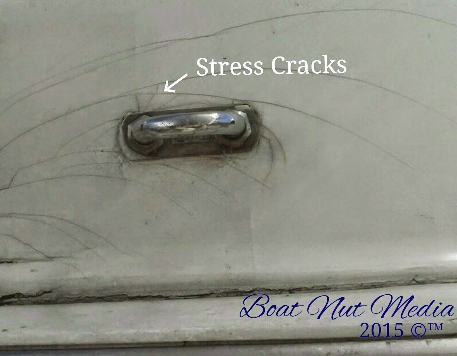
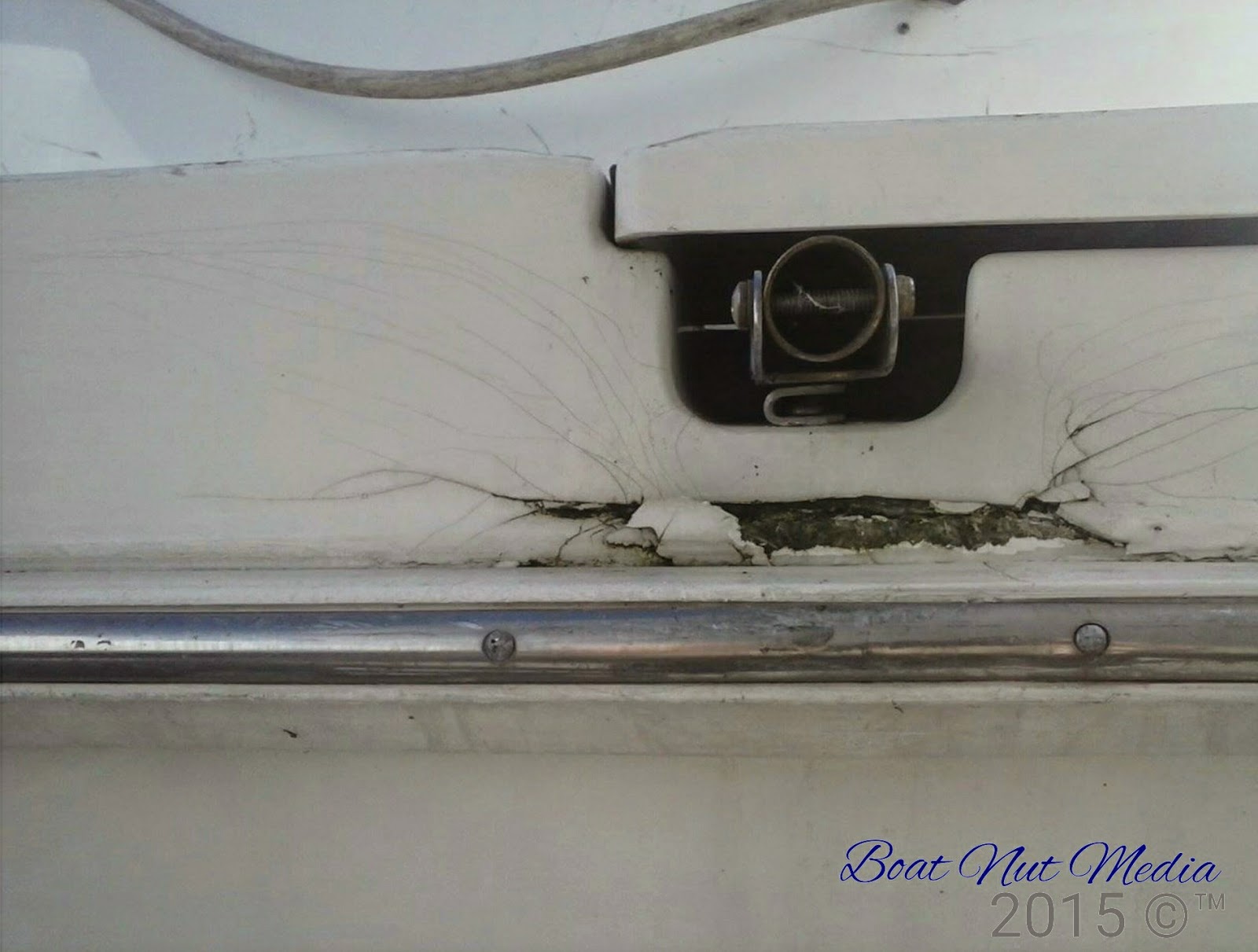
Stress cracks are those nasty spider web looking cracks that occur a point of impact or where there is movement in the fiberglass deck or hull. Movement means an area were a stiff or built up area of lamination meets an area of less lamination. When the material tries to flex stress cracks appear along this line. These types of cracks often occur in a tight radius, under cleats, or at the back edge of your swim platform. What are they? This is were the base fiberglass material under the gel coat has fractured, when a really bad stress crack occurs the gel coat will start to flake away exposing the pink material under the gel coat layer. When you stress or impact the surface of the boat stress cracks will show up, either in the weakest locations or the locations that are overbuilt.  Boat fiberglass lamination construction is a fine art between to thin and too thick. If the material is too thick it will shatter like window glass, it has no give or flexibility. If the material is to thin it will crack from lack of lamination or voids in the lamination process create a reduction of material strength and bond.

1. So how do you determine what your issue is? Well the first thing you should do is take a good look at the damage area, if it is a series of long cracks that have a gap between them of 1 or 2 mm or more start by taping the area with a plastic mallet and compare to an area with no cracks. If it sounds stiff and solid it is likely an overbuilt area or an area were bulkheads or stringers are installed in the molded part. This is the best kind of stress crack to deal with. You will need your Dremel, you will rotor along, following the cracks just past the ends. Only remove the gel coat layer without going too deep into the pink layer. Once you have taken this step along all the cracks, take a rag damp with acetone and wipe down the cracks, you have just taken the gel coat layer off. When the crack is still wet with acetone inspect the crack. Acetone will enhance the visibility of the pink material and you will see if the crack continues through the pink material. If the cracks are still clearly visible then go ahead and rotor a little bit more of the pink material and inspect again. Once you are satisfied that you have removed the crack you will treat the area as if it were a gouge or chip repair. Use the method that we out lined for a fill fair and spray repair in Fiberglass Repair part 1 posting. If you do not have time to do a full repair you can stop these cracks from continuing to grow, simply rotor a dot through to the pink material at the vary end of each crack. Then you can take a small amount of gel coat and fill the small rotor dots, and repair the cracks later.


 2.  If you have an area were the stress cracks are really close and all over each other like a wild spider web, you can do the mallet test again and tap this are and see if it sounds different (hollow or thin). If you notice a distortion in the shape of the area with the stress cracks, it is a sign that this will be an involved repair to fix. In some cases you maybe able to gain access to the inside of the boat and view the lamination, check to see if you can see sunlight through the area. this will allow you to assess how thin the area is. In this case you will need to remove the layer of gel coat that is damaged, for this you will need a grinder with a non aggressive grinding disk. Carefully remove all the gel coat that is cracked without loosing the over all shape of the boat in the area you are working on .If it is for example in a radius, do not grind the radius away just the gel coat needs to be removed. Once the gel is cleared away with a rag damped with acetone and wipe down the area. The pink material will become translucent for a moment and you will see how bad the lamination is damaged. If the pink lamination is badly cracked you will need to remove some of this pink material 1 or 2 mm deep with the grinder. The reason for this is if you fill over the cracks they will reappear almost right away. The procedure for this repair requires you to replace the pink material with a new piece or fiberglass mat to prevent print through (this means the cracks immediately reappearing in your repair). The actual steps to this type of repair are difficult to follow in a written format, however I will do my best to explain the steps to you.
  

1- Apply a layer of fiberglass mat to the area you ground using lamination resin.
2- Allow this area to cure and take your grinder and fair or reshape the area to allow for gel coat fill.
3- follow the repair procedure from post Fiberglass repair part1 to complete the repair with gel coat.

2. Quiet often by the time you purchase all the products and calculate the time involved it is worth hiring a fiberglass repair person to complete the repair described above. If you do not have access to a repair person order the fiberglass repair DVD from Boat Nut Media and see the steps involved in completing stress crack repair. If you go else were for information do not let anyone sell you on the idea that you must use epoxy resin for repair this is non sense. A production boat is made out of polyester resin and using any other resin to repair will create all kinds of problems. Use the materials your boat was made out of to complete all repairs. When you start to introduce materials that were not original to your boats construction your repairs will be difficult and won't likely turn out, they certainly will not last. We think of it as the keep It simple stupid method, the kiss theory will pay off.


Quality and original materials will make gel coat repairs manageable.


READ ART OF FIBERGLASS REPAIR PART 3 HOLES


To guarantee access to all of  Boat Nut Magazine articles, pictures and featured services visit the official Boat Nut Magazine ©™ website. Be sure to reply to the Boat Nut Association registration on our site for the latest Boat Nut weekly and monthly news letters and opportunities.


Copyright 2015 © Boat Nut Media, Toronto, Ontario. All rights reserved. No part of this information/publications may be stored in a retrieval system, transmitted, or reproduced in any way, including but not limited to photocopy, magnetic, or other record, without prior agreement and written permission of the publisher, Boat Nuts Media ©™ No liability is assumed with respect to the information provided.